7.1. About hop-by-hop analytics
Hop-by-hop analytics refers to the process of analyzing network traffic and performance metrics at each individual hop or network device along a data transmission path. Data typically traverses through multiple intermediary devices, or middleboxes, in a network before reaching its destination. Each device represents a hop in the data's path. In complex multi-hop data center networks, VLAN tags are used to identify and help locate the source of problems within the network.
7.1.1. Various ways to use VLANs in a network:
Use VLANs to separate locations and physical links in a data center.
Use VLANs to isolate different applications across the enterprise network.
Use VLANs to identify specific links within a port channel.
Use VLANs to multiplex multiple customers on a shared physical link.
Use VLANs to identify TAP-AGG ports in addition to production VLANs.
7.1.2. How VLANs impact network observability
The potential influence of VLAN tagging on network visibility can be observed in various scenarios. cPacket provides a comprehensive solution that takes advantage of VLAN's different usages to analyze and visualize network observability data. This provides insights that enable you to optimize your network performance, troubleshoot issues, and make data-driven decisions. Utilize hop-by-hop analysis in your network using Monitoring Point Detail dashboards.
Data center VLAN setup
Using VLANs in data center networks helps pinpoint issues more accurately. By using VLAN tags between middleboxes like firewalls, load balancers, or main routers, you can track the path of packets, distinguishing between different pods or network segments. This helps you determine whether packets were observed "in front" or "behind" the firewall or from which specific pod in the data center they originated.
In many environments, four different VLANs are assigned to indicate not only the interface between the two devices but also the direction. Typically, when the interfaces are tapped, the packet broker adds one more layer of VLANs to indicate which port captured the packets.
 |
The VLANs are defined as follows:
Outer VLAN refers to the packet brokering port, which can be a TAP or SPAN.
Inner VLAN refers to the location being monitored within the production network.
There are four possible VLAN configurations to consider.
Production | TAP-AGG | |
|---|---|---|
Case A | A ≠ B and C ≠ D | A ≠ B and C ≠ D |
Case B | A ≠ B and C ≠ D | A = B and C = D |
Case C | A = B and C = D | A ≠ B and C ≠ D |
Case D | A = B and C = D | A = B and C = D |
It's important to know the location of the monitoring point in order to analyze TCP traffic properly. For instance, you need to know if the session was monitored between the firewall and the Internet or between the firewall and the Intranet. To perform analytics correctly, you must match VLAN pairs on each side of the firewall using VLAN mapping. This matching is necessary to identify where packet drops occurred and to measure latency accurately.
Port channels
VLAN tags are used to identify specific links in a port channel. A port channel logically bundles several physical connections into one logical connection. Within a port channel, packets can pass through any of the multiple physical links, each distinguished by a specific VLAN tag, allowing you to manage and troubleshoot the network more effectively.
The following diagram illustrates a load balancer with a port channel configured, with distinct VLANs for each link.
 |
In this scenario, the traffic from LB-0 and LB-1 will use VLAN 21 for one direction of the TCP session and VLAN 22 for the reverse direction. For a complete understanding of the TCP session, the analytics engine needs to know that VLANs 21 through 24 represent the port channel side of LB-0, while VLANs 25 and 26 identify the other side. This will allow for tracking both directions of the TCP conversation through LB-0 for accurate hop-by-hop session metrics.
Network address translation
When both sides of a middlebox employing Network Address Translation (NAT) are tapped, VLANs may not be necessary for the analytics engine to identify the sessions on either side. This is because NAT will change a session’s 5-tuple when translating the internal IP address to an external IP. However, VLAN tagging in the packet broker is useful in this scenario, as it enables quick identification of monitoring points and tracking of sessions across NAT boundaries. Analytics engines still need to use VLAN mapping to associate the receiving (RX) and transmitting (TX) sides of the tap.
Asymmetric routing
In certain situations, such as high-availability connections between data centers, a flow can enter through one router but exit through a different router. This is illustrated in the following diagram. A flow that comes into the data center through VLAN 102 might exit through either VLAN 103 or VLAN 203, depending on the internal routing policies within the data center. VLANs can handle asymmetrically routed traffic, enabling effective flow routing and path tracing.
Deduplication and ignoring VLANs
When a packet broker taps both sides of a middlebox without providing deduplication and the packet analytics engine ignores VLANs, it can lead to inaccurate session metrics. Specifically, this can result in false retransmission counts due to the presence of duplicate packets and inaccurate application latency metrics, as the timestamps from both sides of the middlebox are included, causing incorrect calculations.
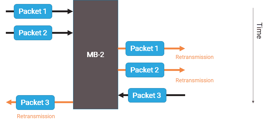
The following diagram illustrates a scenario where packets are incorrectly considered retransmissions. This is a common issue when using Wireshark on a file that combines packets captured from multiple interfaces or locations.
The application latency inaccuracies result from the packet analytics engine's incorrect ordering of packets. For example, when comparing packets from both sides of the middlebox, the engine may mismatch packets from different directions, such as comparing the timestamp of packet-2 from the left side to packet-3 from the right side. This incorrect ordering is due to the engine's sequential processing of packets, which can lead to inaccurate calculations of application latency. As a result, the middlebox's latency is incorrectly included in the calculations, skewing the results.
 |
With deduplication enabled, the packet analytics engine will no longer incorrectly identify duplicate packets as retransmissions, eliminating false retransmission counts and sequence errors. However, this improvement comes with a trade-off: the hop-by-hop analysis will be incomplete, as individual measurements from each hop will be missing. As a result, it will be impossible to determine which side of the middlebox is responsible for packet drops, and latency calculations will still be affected by the middlebox's latency, leading to inaccurate results.
Service provider VLAN setup
VLANs can be used to multiplex multiple customers on a shared link, which is a fundamentally different usage from other VLAN applications discussed previously. In previous scenarios, when the same IP address is associated with different VLAN configurations, it indicates the same host located in different areas of the data center or network. In contrast, when using VLANs to multiplex customers, the presence of the same IP address with different VLANs indicates that these are actually different hosts.
In this scenario, the VLANs are not used for hop-by-hop analytics. Instead, they are used to identify individual customers or separate groups and functions. Typically, this configuration implies that the production VLAN is identical for both receiving (RX) and transmitting (TX) or for both sides of the TCP session, ensuring that each customer or group has its own distinct network identity.